In today’s highly competitive automotive supply chain, understanding the Automobile AC diagram is no longer optional — it is a critical competency for procurement managers, OEM engineers, aftermarket distributors, and workshop operators alike. A well-interpreted car AC system diagram not only accelerates troubleshooting and reduces operational downtime, but also serves as the foundational blueprint for smarter sourcing decisions.
This guide is designed specifically for B2B professionals who need more than a surface-level overview. Whether you are evaluating a new supplier, qualifying components for a fleet, or training your technical team, this document provides a complete, diagram-driven framework to navigate the world of automotive air conditioning systems with confidence.
Overview: Automotive Refrigeration Cycle
The diagram and accompanying table depict the complete cooling cycle of a car air conditioning system, highlighting the refrigerant flow through the compressor, conden sion valve, and evaporator.
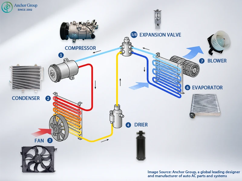
| Labels | Component | System Side | Refrigerant State | Primary Function |
| ① | Compressor | High-pressure | Low-P gas → High-P gas | Pressurizes refrigerant |
| ② | Condenser | High-pressure | High-P gas → High-P liquid | Rejects heat to atmosphere |
| ③ | Cooling Fan | High-pressure | — (air assist) — | Forced airflow over condenser |
| ④ | Receiver/Drier | High-pressure | High-P liquid (filtered) | Moisture removal & filtration |
| ⑤ | Expansion Valve | Turning point | High-P liquid → Low-P mist | Pressure drop & flow control |
| ⑥ | Evaporator | Low-pressure | Low-P mist → Low-P gas | Absorbs cabin heat & dehumidifies |
| ⑦ | Blower Motor | Low-pressure | — (air delivery) — | Distributes cooled air to cabin |
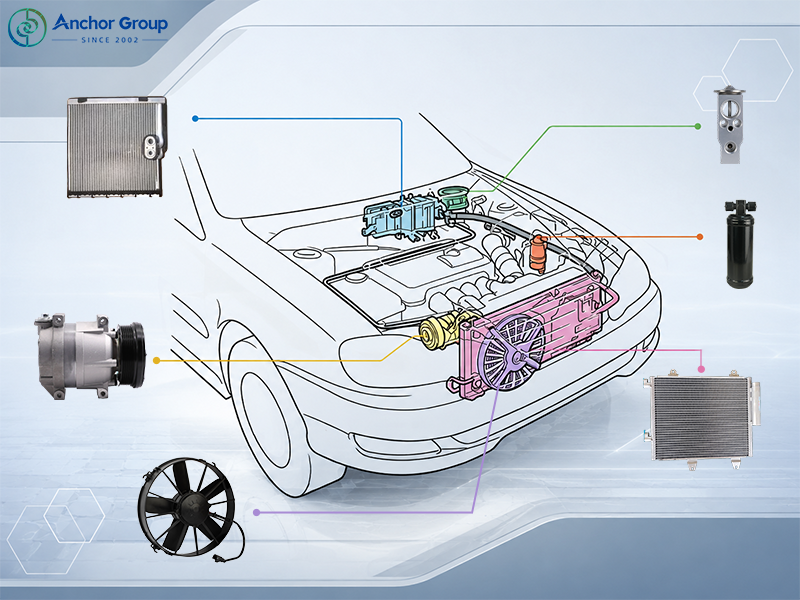
Core Components of Automobile AC Diagram Breakdown
A standard automotive AC system consists of six primary components. Understanding each component’s function within the automobile ac diagram is essential for accurate procurement and quality assessment.
Compressor — The Heart of the System
The compressor is the driving force of the entire AC system and that’s the reason why it is marked as the start in our Car AC System Diagram. Powered by the engine via a serpentine belt and electromagnetic clutch, it draws in low-pressure refrigerant gas from the evaporator and compresses it into a high-temperature, high-pressure gas — initiating the refrigeration cycle.
Its continuous operation maintains the pressure differential that keeps refrigerant moving through every downstream component. Without the compressor, no cooling is possible.
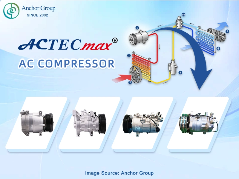
- Position: Engine bay — high-pressure side loop starting point
- Refrigerant state: Inlet: low-pressure gas → Outlet: high-pressure gas
- Drive type: Belt-driven (ICE) / Electric motor (EV/HEV)
- Key spec for sourcing: Displacement (cc), pulley diameter, connector type, oil type
Condenser — Heat Exchanger
Mounted at the front of the vehicle to maximize airflow exposure, the condenser receives the high-temperature, high-pressure gas from the compressor and dissipates its heat into the outside atmosphere. As the refrigerant releases heat, it transitions from a gas into a high-pressure liquid.
The condenser’s efficiency directly determines how effectively the system rejects heat — a blocked or undersized condenser causes high-side pressure to spike, reducing cooling performance across the entire system.
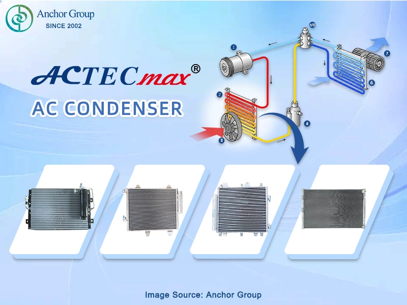
- Position: Front of vehicle, ahead of the radiator
- Refrigerant state: Inlet: high-pressure gas → Outlet: high-pressure liquid
- Works with: Cooling fan (Component ③) for enhanced airflow
- Key spec for sourcing: Core dimensions (mm), tube type, fin density, inlet/outlet fitting size
Condenser Fan
The electric cooling fan is mounted directly behind the condenser and provides forced airflow through the condenser core whenever natural ram air (from vehicle motion) is insufficient — particularly at low speeds, in traffic, or at idle.
Unlike engine-driven fans of older vehicles, modern AC cooling fans operate independently via an electric motor controlled by the vehicle’s ECU, activating automatically when AC is engaged or coolant temperatures rise.
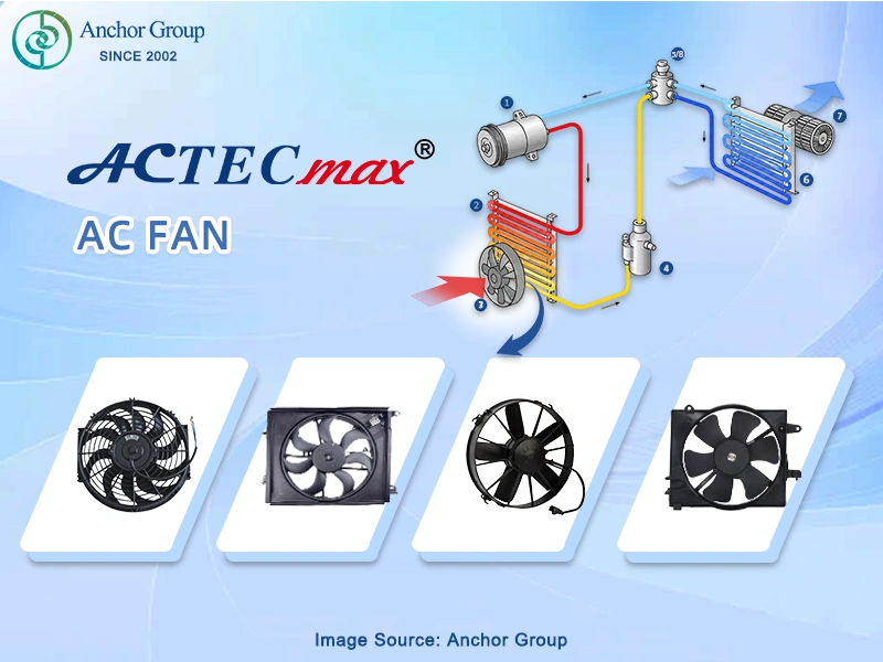
- Position: Mounted directly behind the condenser, engine bay front
- Drive type: Electric motor, ECU-controlled
- Activation: Triggered by AC engagement or engine temperature threshold
- Key spec for sourcing: Fan diameter, blade count, motor voltage (12V/24V), airflow rating (CFM)
Receiver/Drier
Positioned after the condenser and before the expansion valve, the receiver/drier serves as the system’s filtration and moisture control center. Its internal desiccant (silica gel or molecular sieve) absorbs any trace moisture in the refrigerant — moisture that would otherwise freeze at the expansion valve and cause a complete blockage.
In addition to moisture removal, the drier filters particulate contaminants and acts as a temporary reservoir for excess liquid refrigerant, helping stabilize system pressure during varying load conditions.
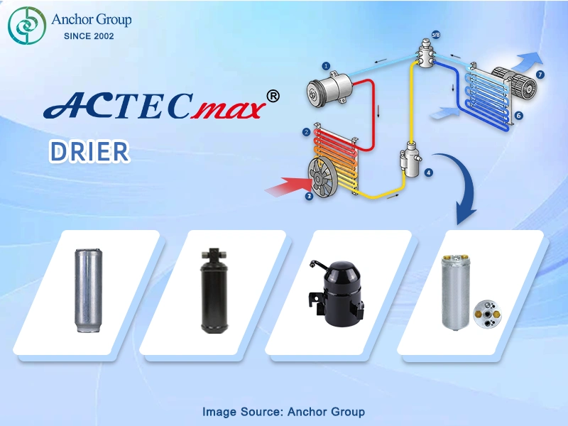
- Position: High-pressure liquid line, between condenser and expansion valve
- Refrigerant state: High-pressure liquid in → Filtered high-pressure liquid out
- Replacement interval: Every 2 years, or every time the system is opened
- Key spec for sourcing: Desiccant type (XH-7 for R134a / XH-9 for R1234yf), capacity, inlet/outlet diameter
Expansion Valve
The expansion valve is the critical dividing point between the high-pressure and low-pressure sides of the system. As high-pressure liquid refrigerant passes through the valve’s precision orifice, it undergoes a rapid pressure drop — causing immediate and intense cooling as the refrigerant atomizes into a low-temperature, low-pressure mist.
Thermostatic Expansion Valves (TXV) dynamically regulate refrigerant flow based on evaporator outlet temperature, ensuring optimal system efficiency across all operating conditions. Orifice tubes provide a fixed restriction as a simpler alternative.
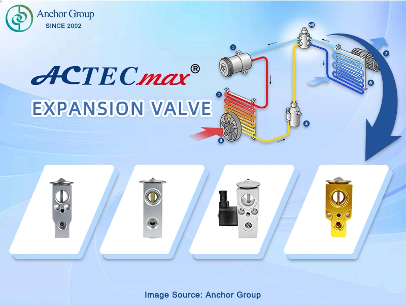
- Position: Junction of high-pressure and low-pressure sides, at evaporator inlet
- Refrigerant state: Inlet: high-pressure liquid → Outlet: low-pressure mist/vapor
- Types: TXV (Thermostatic Expansion Valve) or Orifice Tube
- Key spec for sourcing: Flow rate, superheat setting, thread/block fitting type,
Evaporator — Heat Exchanger
The evaporator is the only component in the AC system that directly contacts cabin air — making it the true source of passenger comfort. Housed inside the HVAC unit behind the dashboard, it allows the low-temperature refrigerant mist to absorb heat from the warm cabin air passing over its fins and tubes.
As the refrigerant absorbs this heat, it evaporates back into a gas. Simultaneously, cabin air moisture condenses on the cold evaporator surface and drains away — delivering air that is not only cooler but also significantly drier and more comfortable.
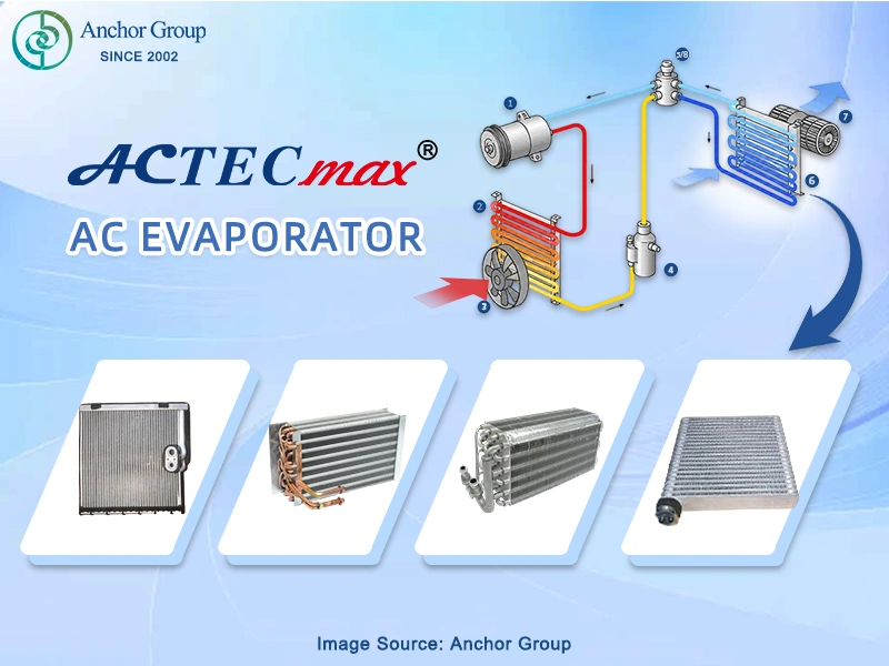
- Position: Inside the HVAC housing, behind the dashboard
- Refrigerant state: Inlet: low-pressure mist → Outlet: low-pressure gas
- Secondary function: Dehumidification — removes moisture from cabin air
- Key spec for sourcing: Core size (H×W×D mm), fin pitch, inlet/outlet orientation, fitting type
Blower Motor
The blower motor sits within the HVAC housing alongside the evaporator and is responsible for drawing cabin air across the evaporator’s cold surface and distributing the cooled, dehumidified air throughout the vehicle interior via the dashboard vents.
Operating independently of the AC compressor, the blower is controlled directly by the driver through the climate control panel. Its variable speed determines the volume of airflow delivered — a functioning blower is essential for translating refrigeration performance into actual cabin comfort.
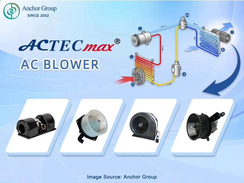
- Position: Inside HVAC housing, adjacent to the evaporator
- Drive type: Independent electric motor, driver-controlled speed
- Speed control: Resistor pack (manual) or PWM module (automatic climate)
- Key spec for sourcing: Voltage (12V), airflow rating, connector type, housing compatibility
Common Faults & Diagram-Based Diagnosis
Using the Automobile AC Diagram to Locate Faults
The Car AC System Diagram is the most effective first tool for systematic fault diagnosis. By comparing observed pressure readings and symptoms against the diagram, technicians can narrow fault location to a specific component or line segment.
| Symptom | Diagram Area to Check | Likely Fault | Action |
| No cooling | Entire diagram | Compressor failure or no refrigerant | Check compressor engagement; leak test |
| High-side pressure too low | High-pressure side | Low refrigerant charge or compressor fault | Check for leaks; inspect compressor |
| High-side pressure too high | Condenser circuit | Blocked condenser or overcharge | Clean condenser; check refrigerant weight |
| Low-side pressure too high | Evaporator & TXV | Expansion valve stuck open | Replace TXV or orifice tube |
| Icing on evaporator | Low-pressure side | TXV stuck closed or blocked filter | Replace receiver/drier; check TXV |
| Refrigerant oil traces at fittings | Refrigerant lines | Hose or O-ring leak | Replace O-rings; pressure test |
Preventive Maintenance Schedule
Incorporating the Car AC System Diagram into a preventive maintenance program significantly reduces emergency repair costs and component failure rates for fleet operators and service networks.
- Every 12 months: Inspect refrigerant charge level; check for leaks at all diagram-indicated connection points
- Every 2 years: Replace receiver/drier or accumulator; inspect hoses for cracking
- Every 4 years: Full system flush; inspect compressor oil level; check expansion valve operation
Explore Our Maintenance Tools
Conclusion
A thorough understanding of the Car AC System Diagram is one of the most valuable competencies a B2B automotive professional can develop. From reducing procurement errors and accelerating diagnostics, to evaluating supplier quality and planning for the EV transition, the system diagram is your single most powerful technical reference.
The key takeaways from this guide:
- Know all seven core components and their position in the Car AC System Diagram — this is the foundation of informed procurement
- Always use a diagram-first approach to sourcing — never order by vehicle model alone
- Understand the high-pressure/low-pressure distinction — it is essential for both diagnostics and system design
- Choose suppliers who lead with technical documentation — it is the clearest indicator of engineering quality
Anchor Group is ready to be your technical partner at every step of this journey. Contact our B2B team today to request a full technical documentation package, product samples, or a partnership consultation.